Thursday, December 6, 2012

English Project

For English class i had to make a 5 page book, and the book had to be decorated with an interest of mine. I chose to make a book with a circuit board attached to it. I first made a simple five page book out of construction paper. After the glue dried, i removed all the large components on the circuit board so it would lay flat. Once all the major components were removed; using rubber cement, i glued the board to the front of the book.
Simple Construction Paper Book

Circuit Board With Capacitors Removed


Final Book With All Major Components Removed

Saturday, November 17, 2012

H-Bridge Circuit for the Underwater Rover

The circuit below is what I'll be using to control the four motors. The Parts list and explanation are below. Because i do not have my motor yet some components are not specified in the parts list. This circuit will be connected to a shift register circuit so four H-bridge circuits can be controlled with three pins connected to the micro controller.


Parts List

R1-R6       1K Resistor
R7-R10     10K Resistor
Q1-Q2      2n2222a NPN Transistor or equivalent
Q3-Q6      Choose a NPN Transistor which is rated for your motor
C1-C3       0.1 μF Capacitor
D1-D4       Choose a Diode which is rated for your motor


The Circuit


INPUT A
INPUT B
MOTOR
HIGH
LOW
Clockwise
LOW
HIGH
Counterclockwise
HIGH
HIGH
N/A
LOW
LOW
OFF


When input A is High and input B remains Low, The motor turns Clockwise
When input A remains Low and input B High, The motor turns Counterclockwise


I am not responsible or liable for any damages or loss you cause with the use of this information and i am not guaranteeing that this will work.

Wednesday, July 4, 2012

LED Spotlights For The Underwater Rover

 The PVC

The diameter of the PVC piping is 1 1/4 inches and so the diameter of the printed circuit board will be the same. I made the printed circuit board the same diameter because the PVC couplers are slightly larger and the printed circuit board will fit snugly inside.


1 1/4 Inch Tee Adapter

The Printed Circuit Board Will Sit Right On Top Of The Inner Ledge  


 The Printed Circuit Board
Here are the printed circuit boards for the LED spotlights. Our design for the underwater rover has four forward facing holes so there will be four sets of spotlights. Each spotlight printed circuit board will have 16 white high brightness LEDs on them. The pictures below are the printed circuit boards i designed with ExpressPCB. I made four because the current design for the rover will have four front facing white LED spotlights.


The LED Spotlight Printed Circuit Board


The LED Spotlight Printed Circuit Board Top Layer


The LED Spotlight Printed Circuit Board Bottom Layer


I am not responsible or liable for any damages or loss you cause with the use of this information and i am not guaranteeing that this will work.

Friday, June 15, 2012

Salvaging Parts From Old Printers

My friend was nice enough to donate his old printers for us to take apart for spare parts. This was very useful for the rover because we able to salvage four high torque DC motors from them. Here are some pictures of the printers being taken apart and some parts removed from them.


The printers partially taken apart

Some parts salvaged from the printers

Complete destruction of the printers


Thursday, June 14, 2012

Underwater PVC Rover Project

One of my favorite hobbies is fishing and every time I go fishing, I always wonder how the fish react to the bait and just how they live. After watching the BBC documentary "The Blue Planet," I was inspired to build a cheap underwater rover to see what's it like under the surface. The rover is going to be made of 1" PVC pipe and parts pulled off of other electronics such as printers and remote control cars.

Wednesday, May 23, 2012

Rain Sensor Circuit

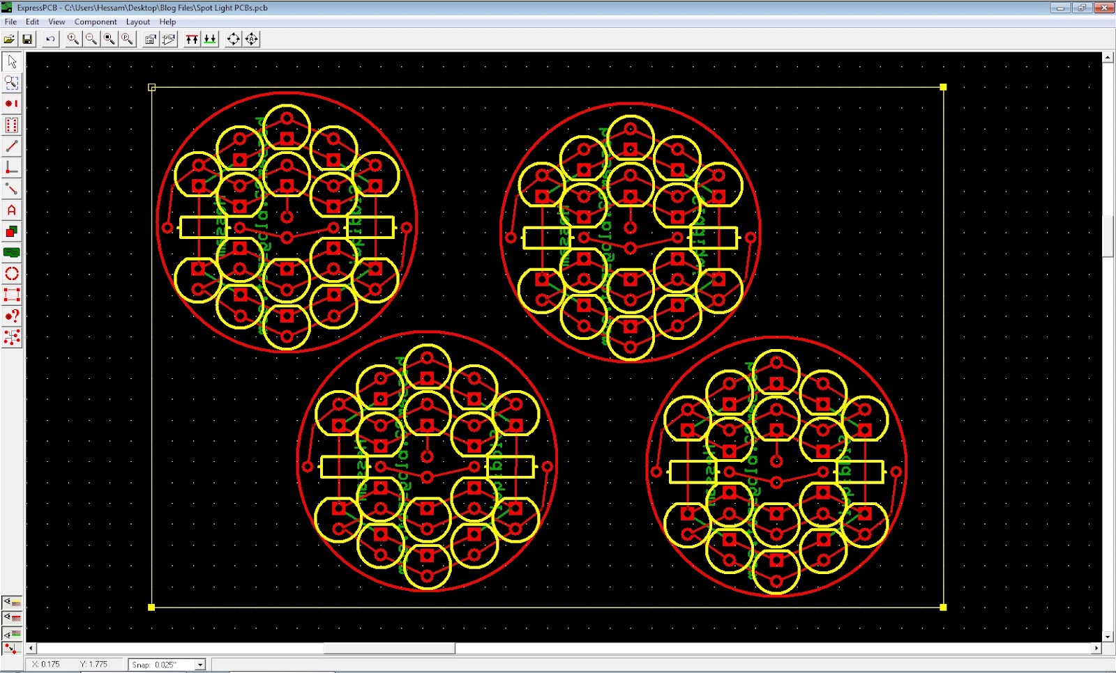
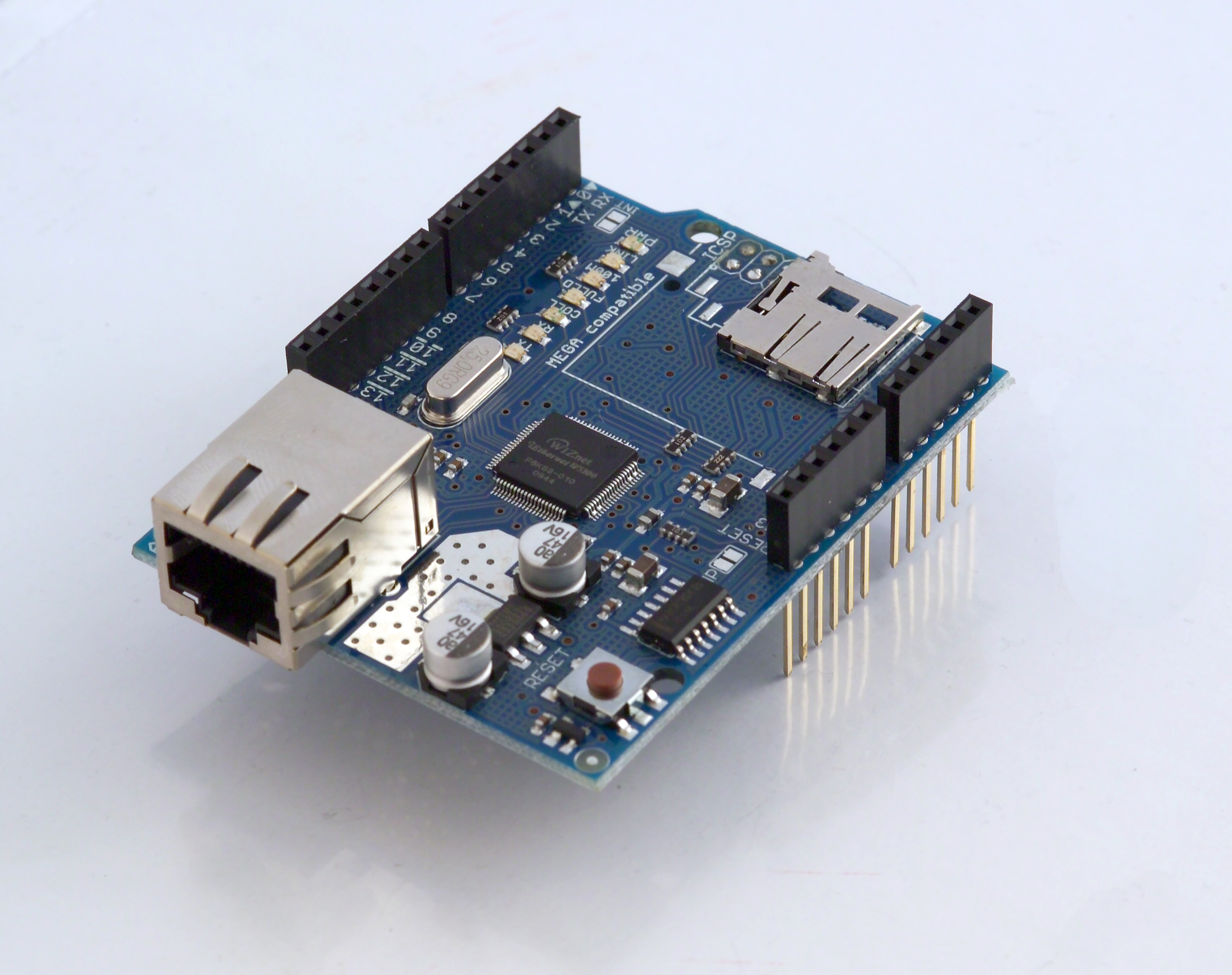
I have started making the first portion of the project which is the rain detector to control the storm shutters. The sensor has been completed and the input circuit has been completed too. The rain detector is very simple and is just two traces on a PCB that do not touch. The concept of this circuit is that when rain drops fall on the PCB, electricity will flow through the water and the Arduino will sense a voltage input. The first picture is the pattern i will be using. You can make the pattern of the rain sensor however you want it, as long as there are two traces on the board that do not touch. The first picture is the pattern i will be using for my circuit. The second picture is just an example of a random pattern you can have. I have completed the input portion of the rain sensor and is shown below. The 10K ohm resistor is temporary and may or may not be charged when the rest of the circuit is built. The rain sensor does not have to be connected to an Arduino. You can make your own circuit that simply determines if there is connectivity between the traces on the rain sensor PCB.

The pattern i will be using

A random pattern i made

Rain sensor input


The Code

/*
    Hessam Siddiqui
    05/23/2012
    hessam93.blogspot.com
    Rain sensor test circuit
*/

void setup()
{
    Serial.begin(9600);                                    //Initializes serial to 9600 bits per second
}

void loop()
{
    int rainSensorValue = analogRead(A0);   // Reads the input value from analog pin 0 and assigns it  to    rainSensorValue
    Serial.println(rainSensorValue);               // The value of rainSensorValue is printed
    delay(100);                                            // A small delay so the output doesn't scroll to fast
}


I am not responsible or liable for any damages or loss you cause with the use of this information and i am not guaranteeing that this will work.

Sim Card Cloning

I work at an electronics store and we deal a lot with sim cards, so i was looking on the internet to learn more about them and i found this interesting page about cloning sim cards. It's very interesting and i might make it soon after i am done with my project to electronically control my house. Also if you do decide to use this make sure it's for fun and not to harm anyone like the article says and i am not responsible for how you use it.

http://www.5ne.org/sim-cloning/


All of this information is open and i am allowing anyone to do anything they want with it without requesting my permission. However, I am not responsible or liable for any damages or loss you cause with the use of this information and i am not guaranteeing that this will work. Use at your own risk

Sunday, May 20, 2012

Major components of the project

Major components I might be using:

Either a arduino UNO or mega (depends on the amount of devices I want to control and I'm too lazy to use shift registrars)
Xbee for wireless control of other rooms
Pc to control the arduino
Ethernet shield (to control it over the Internet but that will be later. Keeping it simple now)
Photoresistor to control blinds (depending on amount of light)
Rain detector to control the storm shutters
That's all I can think of now but I'll keep updating when I think of more stuff

(Ethernet Shield)
(Arduino Mega)
(Xbee)

Saturday, May 19, 2012

Other things to control in the house

Since I can't control everything in my house with a single knock control (well I technically could but it'd be very confusing to remember all the knock) so I'm going to use my arduino micro controller and use either a pc interface or a smartphone to control it. Circuit and design should be up pretty soon!

Wednesday, May 16, 2012

Knock Sensor To Unlock Car Door

I saw this project a couple days ago and thought it might be interesting to put it in my car for something. I tend to lock myself out of the car a lot so i was thinking about having it unlock the driver door for three to five seconds then lock itself again. 


Knock Detecting Door Lock by Steve Hoefer:
http://grathio.com/2009/11/secret_knock_detecting_door_lock/